How to build the pc-switch
What sol?
Prerequisites
For DIY you need a basic soldering setup:
- Soldering iron
- solder
- optional but highly recommended: A soldering helper/hand
Parts needed for the PCB
- WEMOS D1 mini (The ESP8266-12F from AZDelivery is a popular clone here in Germany)
- 2 x Optocoupler EL817
- 2 x Resistor 220 Ohm
- Pin header for power pins: 2x1, you can use straight or angled versions
- Pin headers for front panel connectors: 3x2 pin headers, you can use straight or angled versions
- Pin headers for motherboard:
- 3x2 pin headers, you can use straight or angled versions
Additional parts for connecting the pc-switch
- 6 x female-to-female jumper cables to connect to the motherboard
- 6 x female-to-male jumper cables to connect to the front panel connectors
- 2 x female-to-female jumper cables to connect to power (use USB or other pins from your motherboard which are always on)
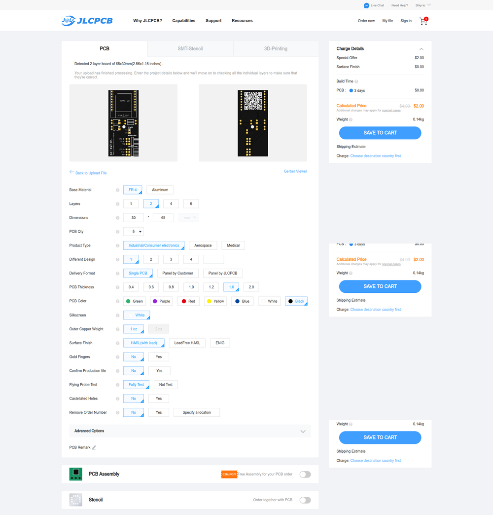
Ordering the PCB
Download the Gerber file Got to https://cart.jlcpcb.com/quote Upload the file and adjust your order
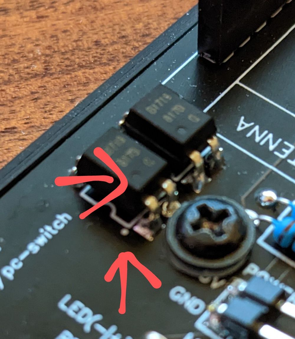
Soldering
Resistors can be soldered either way, you can not do anything wrong here. Optocouplers need a specific orientation. You need to align the small circles on the board with the circles on the optocoupler.
Flashing the software
-
I think it goes without saying but you need Home Assistant running somewhere.
-
Install the ESPHome Add-On:

-
Plug in the device via USB to your PC or the PC which is running Home Assistant
-
Copy and paste the YAML from GitHub: https://github.com/ajfriesen/pc-switch
-
Now your pc-switch should pop up automatically in the device section

Connecting to a PC or Server
- Check if your motherboard supports always-on USB and enable it if possible(sometimes this setting is in a really weird spot)
- Connect your pc-switch to some USB header for power. Check the pins on your motherboard manual. You just need to use 5V and GND. (If you don’t have always-on power you can run a USB micro cable into your case as well)
- Connect Reset, Power and Power LED with your board.
- If you want to use the power button and power led on your PC case then connect those as well.
Now enjoy automating your PC.
- Turn it off or on at a specific time
- Add another button (like the Aqara ones) to Home Assistant and use that for power on/off
- Connect your voice assistant like Google Home to that switch with Home Assistant (That is what I did🙂)
Last modified February 12, 2023: Add initial docs folder for hugo site (1aa1bb5)